Friday, September 01, 2006

Left atrium segmentation

It is quite a tedious process to segment the left atrium from an MRI, interactively, using a recursive-region growing segmentation algorithm. Small changes in threshold levels causes a major change in the segmented volume. The segmentation is performed within a region of interest (a user-defined cuboid). This ROI is the volume within which the human user thinks is where the left atrium is expected to lie by looking at the MRI.

I totally quite yet dont understand if we can assume whether the blood has filled the entire left atrium, in the post-angiograph. I suspect, frm initial segmentation results, that there could be parts where the blood hasnt completely reached the left atrium. However, this is total image acquisition issue. But a burning question, when is a post-angiograph taken? I can definitely confirm that I have seen post-angiographs where the radiocontrast-agent hasn't yet reached the left atrium. But I wonder, why is that the case? Shouldnt post-angiographs be taken when the patient has a complete circulation of radio-constrasting agent blood?

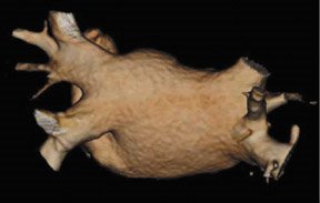
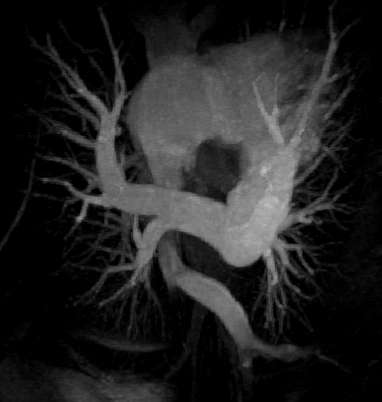
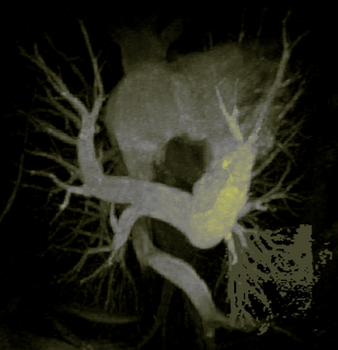
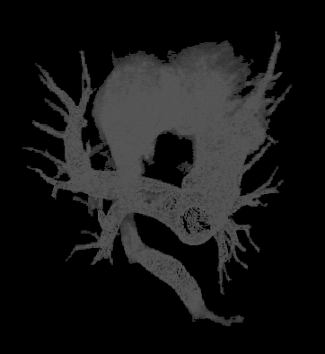
Following is what would be, my dream segmentation of the left atrium:
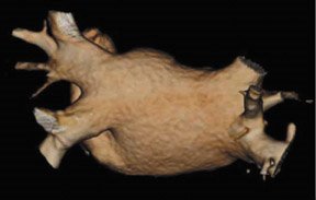


As you can see, the number of branches of the PV drainage branching out of this atrium is what makes our lives difficult, and thus giving people like us the opportunity to do a PhD.

Thursday, August 31, 2006

Left/Right atriums and ventricles in MRI

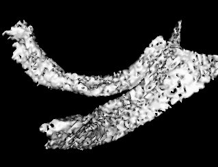
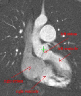
After doing a thorough google search, it was difficult for me to locate an MRI showing the left and the right atriums, together with the ventricles. I am posting some MRI slices obtained by subtracting pre and post-angiographs to remove bone structures. What you see in these MRIs is blood travelling through the different vessels and heart structures. 'Post-angiograph' is after the blood is injected with Gadolinium (Radiocontrasting agent) and what you see in the MRI here are the bright regions indicating the blood travelling through the different structures. However, a pre-angiograph of the thorax region shows nothing really, and only the bone structures.


Above is an MRI showing the heart with a long-axis view. But beware! What you see is only the blood travelling through the different regions of the heart, and the radiocontrasting agent in the blood making it appear bright in the MRI.


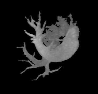
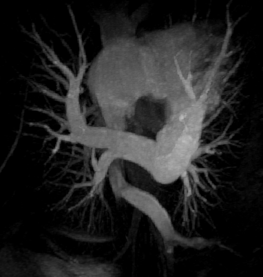
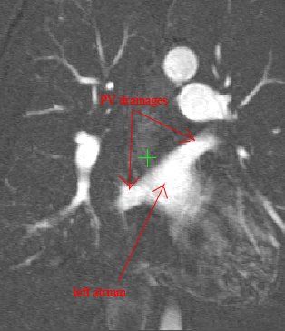
Above, is a better picture of the left atrium together with the PV drainages. There are actually more drainages to this atrium, and these appear in other slices. The left atrium is situated right next to the right atrium and extends to behind the right atrium.


Thursday, August 24, 2006

Some VTK tips and PhD progress

Its been a while since i have written to this post. I have been fiddling around with VTK. Its quite hell of a learning curve when you are teaching VTK to yourself. Here are few things I have to say about VTK:

1) Its amazing that the visualization library is open source.

2) You will hate VTK from the day you start learning it, till the day you master it. It's the most wonderful thing when you have mastered it.

3) It's a nightmare if you can't debug your VTK programs, make sure your debugger works with VTK

4) Make sure you know how to look into VTK documentation. The documentation has been
generated by DOxygen, and make sure you know how to find functions, how to list them alphabetically, etc. It really helps if you can know how to quickly search through documentation. Generally, I look through 'VTK Class members' (see here ), class members are functions ofcourse. There is an alphabetic index on top of this page, so if you are searching for 'foo', click on f and search through page.

5) The best way to solve your VTK problems is by going through the VTK forums. Their search utility is not the greatest, but you can search intelligently, once you know how their search engine behaves. Here's the VTK forum.

6) ... and the bottom line: if you are not an avid C++ programmer, you will be surprised at how small things can cause segmentation faults within a VTK program (make sure you have called your constructors, etc). Have patience, once you know how VTK behaves, you will enjoy using the VTK library.

7) .. and hey .. dont forget to get a dedicated graphics card for your PC (not the ones which come with the motherboard). It really helps with your renderings!

My PhD progress is quite good, these days I am trying to create an interactive segmentation tool using VTK + Imperial college's ITK + FLTK. I had trouble trying to embed VTK windows into FLTK GUIs, and I was successfully able to do it. There are third pirty libraries out there such as the vtkFltk library (just 2 files), which is the most easiest to use.

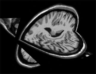
Apart from this I am able to view the MRI volume using two orthogonal planes (which slice through the volume), here are orthogonal views of a brain MRI:


And here's the hypothalamus segmented by allowing the user to specify a region of interest:


These were segmented using a region-growing approach with a simple upper-lower threshold technique. This requires a great deal of trial and error to choose the correct upper and lower threshold limits.


Friday, May 26, 2006

Finally some segmentation. Flattening 3D volumes to 1D array

All this time I was thinking my region-growing procedure was running out of stack space. However, after some debugging I discovered that I was doing something wrong in the way I was transforming my 3D volume to a 1D array. Just sometime ago, when I was doing this course on Advanced graphics visualizations, I realized that you could store a 3D volume in a 1D array, and essentially the same goes with a 2D array. So if your 3D volume has dimensions x, y and z, a 1D array can be used to store the scalar value at any position (x,y,z). As you would have already imagined, the 1D array runs from index 0 to (x*y*z - 1). All you need is a mapping function that maps co-ordinates (x,y,z) to an index i in your 1D array. In your application, you might also require the inverse of this, i.e. from i to (x,y,z). The equations are quite straightforward:

Mapping function from (x,y,z) to array index i:
index i = (z * X * Y) + x + (X * y);
(where X, Y and Z are: 0<= x <=X and 0 <= y <= Y and 0 <= z <= Z)
and mapping from index i to (x,y,z):
z = i/(X * Y)
y = (i - z * X * Y)/(X)
x = i - (z * X * Y) - (y * X);
I was going wrong with these equations. Finally when I had them corrected, to ensure that these were correct, I wrote a verification program to test that the equations were invertible ( i.e. fg(x) = x if f = g^-1 ).
Both the recursive and non-recursive region-growing procedures now work fine. I had them tested on an artificial image of a brain MRI. I will be posting more results on the segmentation. Here are some preliminary results.
The procedure accepts both local and global thresholds. Local thresholds are thresholds imposed on the direct neighbors of a voxel, and these threholds vary from one voxel neighborhood to another. For e.g. I am using a threshold whereby every voxel in the region is allowed to include into the region a voxel in its neighborhood which is within a certain intensity +/- 5 for instance.
It so appears now, that if we try to pinpoint a small vessel and try to segment it using a small global threshold value, the entire volume gets segmented. However, the entire volume segmented comes out much "darker" than the original volume in the Maximum Intensity Projection (MIP) rendering.


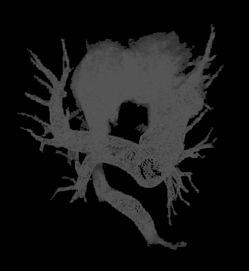
The image on the left is a MIP rendering of the segmented volume by using a seed point close to the atrium of the heart, and by using threshold values of 60 100. The image on the right is a MIP rendering of the segmented volume by using the same seed point, but using thresholds of 0 and 1000. The image on the right is essentially the entire volume and technically with nothing segmented.

Saturday, May 20, 2006

Installing ITK at home

I have been trying to get ITK (Imperial college's ITK NOT Insight Toolkit) running at my home using Visual .NET 2003. Apparently ITK has problems compiling in .NET 2005. The errors which show up are correctable and it becomes evident that .NET 2005 has improved their cl compiler. There are some errors that has to do with assigning a const char* to a char* to which .NET 2003 doesnt complain which it should have.

Getting down to important things to remember when installing ITK, one has to make sure that VTK and FLTK is compiled using the same compiler or else it might throw some errors. FLTK also needs to be compiled with the FLTK_USE_ZLIB, FLTK_USE_JPEG, FLTK_USE_PNG options set to off. This is assuming that our system does not have ZLIB, PNG, JPEG libraries and we make FLTK build the libraries for us.

It is also important to compile ITK under Release mode. There are different compile modes in Visual .NET 2003 (i.e. Debug, Release, etc). The IDE usually defaults itself to the Debug mode. Setting .NET 2003 compiler to the Release mode makes the compilation process a lot quicker. Technically we should be able to compile it in Debug mode, but I havent tested it.

If you are going to be using VTK volume rendering libraries, strangely the vtkVolumeRendering library (vtkVolumeRendering.lib file in the vtkVolumeRendering folder) is not loaded as an additional library by default to the visual .net 2003 linker. One can easily manually do this, by going to Project properties -> Linker -> Input.

One last word: watch out for the errors, ignore the warnings. Some of these errors can actually be fixed if looked into more closely.


Thursday, May 18, 2006

More on Region growing for vessel segmentation

The problem of using a trivial region growing algorithm which uses a one or two-fold threshold as its growing-criteria is that it is bound to "explode" in the case of heart-vessels. What usually follows this explosion is a "stack-overflow" exception which results from the large amount of stack space taken up by the recursive region growing process. I have been experimenting with a recursive region-growing algorithm, and it runs out of stack when run on the visual .net C++ compiler despite increasing the stack size to several hundred megabytes (using the /STACK option in the linker, or the /F option of the compiler). What actually happens is that the region explodes into the atrium of the heart where it ultimately runs into a stack exception. However, the algorithm segments correctly without a stack-exception if the lower and upper-thresholds are set to point to high-intensities (scalar value of 80-150).

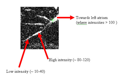
Grey-value intensities in contrast enhanced MR angiography is directly proportional to the amount of blood flow in a region. The atrium of the heart presents high intensities, the reason of which is quite obvious. However, the venous drainages also present high voxel intensities in certain regions. I presume this is related with the high blood-pressure in these areas due to the narrowing of the vessels towards the drainages. Although we would expect the entire drainage to be of high-intensity, however, this is not the case. Close to the endings, we come across low intensities. So now this variation in intensity poses a challenging problem when using thresholds, i.e if we were to select a threshold for region-growing segmentation of the venous endings, we would have no choice but to pick a low-threshold value (in-order to capture the minute vein endings) and a high-threshold in order to capture the parts of the vein-endings where the blood flow is high. Since the Atrium of the heart has a high-intensity value, this causes the algorithm to explode into the atrium, causing a stack-exception at some point. The stack-exception can also be equally attributed to the lower-threshold value, since this threshold value causes the algorithm to further leave the atrium and flow into the numerous vessels which branch out of the atrium.

Following is an illustration of a veinous drainage as seen through an MRI contrast-enhanced angiography. This is only a slice through the entire volume captured in the MRI.

After meeting with Prof. Daniel today, he suggested to me to further investigate the possibility of increasing the stack space and to see if the recursive algorithm can be made to work. The best possible result is to get the entire MRI segmented by using low-high threshold values. I also suggested to him how people have been performing brain vessels segmentation using an atlas-based region growing approach as described in "Region growing segmenation of brain vessels: an atlas based approach" by N. Passat et. al. Brain-vessel segmentation seems to be different from heart-vessel segmentation; in essence brain vessels dont branch out of an "atrium" like structure.

Prof. Daniel suggested to me to use a non-recursive approach to region-growing whereby we could keep the growing-region to a spherical-like shape at any time instant. A recursive process tends to grow out the region in one direction at a time. Making the region grow out spherically could allow us to develop better cost functions which for example could utilise the compactness (surface area / volume) of the growing-region.

The 9-month transfer report is due soon.

Tuesday, May 16, 2006

Experimenting with Region Growing methods

I have slacked off a bit due to tasmia's arrival to London and my exams. I havent been working for the past 4 days (which incl. 2 days of the weekend). I was able to install Visual studio 2005 at home, so which means I will be able to work on my experiements from home. My Google interview is soon, and so I will have to prepare for that as well.
I will be reading Region growing based techniques for volume visualization by R. Huang et. al. They have used simple statistics for region-growing criteria selection. I might get better results than the ones I have below (using simple thresholding).


I have used a recursive algorithm which uses a two-part threshold. The recursion is on the 6 neighbors of a voxel (2 in each direction -> 2 in x, 2 in y and 2 in z). The image above is a MIP rendering of the volume. The segmented region is show in dark one-color green.

Saturday, May 13, 2006

Final exams and preparation week

I will soon be posting on the 3D segmentation I was able to do, only to a certain extent, using a recursive region growing algorithm. The criterion for region growing is simple and I am using an upper and lower threshold. This is known to produce "holes" in the MIP rendering of the segmented region. It seemed quite clear later on as to why such local discontinuity occurs in the rendering. Since we are doing a Maximum Intensity Projection, the maximum intensity function around a neighborhood of the segmented region is not guaranteed to be continuous or approximately continuous.

Using a recursive region growing algorithm with a criterion like the one I am using at the moment (thresholds) is just the beginning. It is popular to use other criterions, such as the Fischer's criterion. Most of these really boil down to using some sort of statistical mesaures. I am looking to first try and see how well it works if I used a simple idea of a pixel fulfilling a group if it is within some n number of standard deviations.

Apart from research work, I have been busy preparing for finals for the Machine vision and Advanced graphics and Visualization courses I took this year. Imperial exams are very thought provoking, much like the ones I "reckon" I used to get at U. Toronto.

Thursday, April 27, 2006

Region growing segmentation


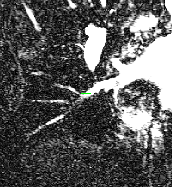
Region growing segmentation seems like a relatively easier thing to use to segment the pulmonary venous drainages. I will be trying to implement a Seeded Region Growing segmentation to start extracting the drainage patterns. However, I anticipate that Region-growing might not work perfectly with veins. The problem with region growing is that it seems to explode and find its way out somehow out of the region which we are interested in. To get a jist of how difficult segmentation might get, have a look at the MRI image above. I wish everyday that MRI image acquisition was clearer.
In near future, I will also be looking at other image segmentation techniques used in medical imaging. There is a good piece of literature out there that explores out all the different techniques that have popularly been used in segmenting medical images. Here's the paper.

Wednesday, April 19, 2006

VTK Error

I have been stuck for about a couple of weeks trying to get rid of this error
vtkVolumeRayCastMapper Cannot volume render data of type short, only unsigned char
or unsigned short.
that I have been getting when I was trying to MIP render a GIPL image. I was finally able to resolve the issue, with Prof. Daniel's help. I have looked around the web for a solution, and all of the solutions that I have looked at didnt help. Infact, people working with ITK (Insight ITK) commonly face this problem when they are trying to render an ITK image.

The solution is simple, only if you knew the vtk classes inside out. Anyone would have guessed what needs to be done here: we simply need to make sure that the scalar values we have in our vtk data set (vtkStructuredPoints for e.g.) are non-negative values. Well, if you have negative values, you want to make sure that you can scale them back to the set of positive real numbers. The way you do this is by first determining the minimum and maximum of your scalar values and then setting the minimum to be 0. So if -5 is the minimum, you set it to zero and add all the other scalars by 5. Once you have non-negative values, all you now have to do is pass the vtk data through a small pipeline. A pipeline is an important concept which I learned about today. Most VTK textbooks have this explained well. What it really is that the output of a filter becomes the input of another filter, and this is done by using common vtk functions such SetInput and GetOutput. Going back to our discussion, once we have non-negative values, we need to cast and make sure that we can safely cast. If you have scaled your scalars properly, it should be a safe cast.

vtkImageCast *vtkImageCast = vtkImageCast::New();
vtkImageCast->SetInput(vtkImage);
vtkImageCast->SetOutputScalarTypeToUnsignedShort();
....... // somewhere down the line ...
volumeMapper->SetInput(vtkImageCast->GetOutput());

As you can see, a new vtkImageCast object casts the vtkStructuredPoints vtkImage object's scalar values to unsigned short and then the GetOutput function is called to feed the output to the renderer.


Saturday, April 15, 2006

Moving homes and other stuff

I have been spending most parts of this entire week either at Glu or trying to move out to my new apartment. Looking for a place to stay in London is harder than solving an optimization problem with defined constraints. My interview at Google is very soon and I am very excited aboout it. It is one thing that I noted about Google that is atleast different from Microsoft, Google's hires a lot of "academically" bright students, and I mean students from the good schools with the good grades. I have been reading a couple of profiles and quite a handful of them even have PhDs. I think Microsoft puts much more emphasis on programming quality and ability than any other thing.

I have been working on my MRA visualization. Somewhere in VTK i am having problems trying to render an ITK image. Apparently some common VTK rendering functions (such as ray-casting, MIP) can only render volumes with voxel scalar values that are of type unsigned short/char. The ITK images which I have are of type signed ints. It does not make sense to me why VTK designers would want the format to be unsigned short/char. unsigned makes sense, but why short and not an int?

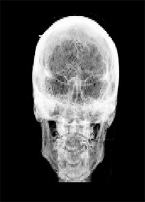
At the same time, I am also working on a coursework which was due ages ago. Here is a rendering of the skull using Back-to-front (BTF) compositing. The rendering is very basic since I have only used a single threshold and no lighting model. I have also limited the colors B/W as I wanted to get an X-ray like image. The original volume is from a CT scan though. So here you go, your CT to X-ray converter.


Friday, April 07, 2006

ITK + VTK Compiled

After a long haul, VTK and ITK finally compiled. The problem was with having VTK not installed properly on my machine. The thing with open source software is that the installers (if any) are not that great. Sometimes, as it did with me, it installed a version of VTK that was not fully compatible to run on my OS. The best thing to always do is to download the source and compile it using your compiler. That's what I did with VTK, when I realized that it was not working with ITK. There were also problems with Project (ITK), and things needed to be updated. I also had to install FLTK in order to install rview. rview apparently doesn't work without FLTK. There are also other little things that I should be careful about: for e.g. turn the Advanced options on when CMake-ing, and make sure you have put the GL/gl.h and glut32.lib files under your compilers lib folders (such as vc7/lib). However, as a piece of advice, the best thing to do is to read the errors carefully when compiling ITK and to stay calm when errors > 100 show up (after which vc .net stops compiling further :(( )


Wednesday, April 05, 2006

A thing called CygWin

CygWin is a blessing to the windows operating systems. Basically it makes your Windows system acts like a UNIX OS. It provides some basic UNIX OS functionality together with programming development tools like GCC, etc. You could run xemacs/emacs on cygwin as well. So, if you are an emacs person and run windows on your PC (a rare combo) you should probably get CygWin.

CygWin also allows X11 forwarding through its CygWin/X package. So basically, you could connect to a remote linux/Unix server and get the graphical output on your WinOS. And fundamentally, Cygwin consists of a library that implements the POSIX system call API in terms of Win32 system calls.

I have been trying to setup CygWin/X. And today I got stuck trying to configure X11 forwarding and setting up display settings, although I had done it some time before. Basically you need to call the startwin.sh script, as described in here. After that you can ssh to your remote host on the X-window (window that appears after you run startwin.sh).

Tomorrow I get to meet Prof. Daniel. My ITK build is now completely messed up. I cleaned up the build and now after re-building it gives me errors which I never got before. I have written a basic visualization code. I also need to invest some time in getting my Adv. viz. coursework program code to work.

Tuesday, April 04, 2006

For most parts of the weekend, I have been spending my time at Glu. Its seems like its been a while since I have taken time off, and Sunday was finally a holiday for me. I am working on my Advanced graphics coursework that requires me to render a brain CT scan using fundamental rendering algorithms. The coursework looks complicated and I am right now trying to run it on Windows. ddd Debugger is horrible. I was stuck trying to figure out what an error meant, which popped out everytime I ran ddd on the executable. To make a program debuggable, you must gcc it with a -g switch. Ah well, ddd has a poor array analyzer. I remember back in my MSc days, when I used visual C++ 98 to examine arrays, and it was so much simpler.

The coursework requires openGL. And to my surprise, the download links to SGI's openGL does not work! I recently learned that Windows OS ships with OpenGL 1.1. I have no clue about where the exes and dlls are located.

My PhD work this week is currently at a Standstill. I am still trying to do my visualization code. On Monday I had translated some of the VTK python/TCL code to C++ for visualizing using some basic rendering function. I cant remember what rendering I used, but thinking about it right now, what could be simpler than MIP rendering??? :) Strangely, at this point I cleaned my ITK build, and it is not compiling anymore. There are scores of errors and perhaps I need to go to Raj or Prof.


Wednesday, March 29, 2006

Stuck with VTK

It's getting a nightmare trying to compile programs which use VTK+ITK. Today I spent the entire day trying to learn how to use VTK for visualizing a dataset. After our meeting I learnt how ITKImage has functions that can convert a gipl image to a vtk structured point set (i think thats what they are called). There is also an .exe called "convert" that converts gipl to vtk format.

The next two days, I will be spending mostly at Glu.

Meeting with Prof. Daniel

It was a short meeting that we had today. We talked about how important it was for me to get the visualization done as quickly as possible. From there on we are planning to segment the images somehow first using some fundamental segmenting algorithms like Region growing. At some point we intend to be able to automatically get data for creating a Statistical shape model for the pulmonary drainage veins.
I also discussed my meeting with Dr. Tim Cootes at Oxford. After showing him the different drainage patterns, Cootes suggested that it would probably be a good idea to use more than just one shape model to describe a single pattern. However, I also explained to him how difficult it was to acquire images for patterns which are rare.
After discussing the rarity of the patterns, Prof. Daniel suggested that it would probably be a good idea if we could create models for the rare patterns with whatever data we have, and then declare that the model has some limitations. He also said that we could find out what proportion (e.g. 95%) of the data it explains (not clear on this)

non PhD: How do you export highlighted syntax source files

Someone was asking me how you export a highlighted-syntaxed file to a word document. This is something I have never thought of in all the years I have programmed and created reports. Anyways, there is a solution. It happens that one of the editors out there has an export function that enables you to export its highlighted content to various formats such as PDF, RTF (works in Word), XML, etc.
The editor's called SciTE and here's the link to their page.

Tuesday, March 28, 2006

Subtraction works

I finally was able to subtract a Post Angio image from a Pre Angio image. The images are MRIs showing the pulmonary vessels. Subtraction, although a very trivial procedure, took me some time to figure out since I was new to the IDE.

The subtracted iamge reveals the blood vessels. Daniel has suggested that I perform a MIP (Maximum Intensity Projection) rendering on the vessels to analyze the structure. MIP can be easily implemented using the VTK library. I am doing some background reading on basic Computer graphics concepts such as volume/surface rendering. I have got hold of some papers and a book on the VTK library.

Installing Daniel's ITK

I have been trying since weekend (25th March) to set up Daniel's ITK. It has really been difficult. Thanks to Raj. He helped me a lot to set up ITK on Visual .NET. Sometime I need to sit down and write all the installation procedures.

It's simple, first you need to checkout the code (which vip calls Project) from CVS. I have been using Tortoise CVS on windows. You then need CMake to install the binaries, this step is important as CMake produces code optimized for your compiler. Next, it's just a matter of opening up the solution workspace on Visual .NET and building the solution.

What got me the most was how we are supposed to deploy code that we write, which uses the ITK. So for example, if we write code which uses the ITK library, our file (.cc) needs to sit under project/applications. CMake needs to install the binaries once again, and the solution needs to re-built. Its a nuisance doing it over and over again, but thanks to the Visual .net IDE which only compiles files which got recently changed. Look for an option which only builds the file and not the entire solution.

Oxford Uni. for Spring school

I spent a week (Mar 19- 24) at Oxford attending lectures given by some prominent researchers in the field of medical imaging. It was a great learning experience, and I enjoyed my time greatly. For any one interested in the Oxford Spring school, here's the link to their webpage.

The entire conference costs around 500 pounds, and the accomodation is included. We were given accomodation at St. Anne's College. It is a good idea to take your laptop with you. I survived the whole one week without a computer.

I met some people there who are also new researchers in the field of medical imaging. Notably, Arif Asif Qazi at the IT university of Denmark, and others. It was funny that I met a few people from Imperial College for the first time there. Ioannis (neurologist) and Mustafa Anjari (medic) are both working at the Hammersmith hospital, which is also a part of Imperial College.